Common pitfalls when installing HVAC duct sensors


This is the second in a series of three blog posts looking at common pitfalls when installing HVAC sensors, focusing on physical measurement errors that are caused by incorrect installation. This post focuses on common installation errors for HVAC duct sensors.
Temperature differences
For duct sensors, the most important source of measurement errors is temperature differences between the air inside and outside the duct, for example if you’re trying to measure outdoor air conditions by putting a duct sensor in the intake air duct. There is usually quite a big temperature difference between duct air and outside air temperatures, causing heat to flow through the duct and either increase or decrease the temperature indicated. Of course, this also then distorts humidity measurements, particularly if there are large temperature differences. If there is high humidity in the duct with a lower temperature outside the duct, it can cause condensation. With low flow speeds the effects of the heat leaking from outside the duct is more pronounced. For accurate measurements it is important to avoid any of these situations.
You have to be very careful when using insulated ducts as they increase the temperature difference between the duct and the environment. You may need to open up the insulation for the sensor and put it inside special insulation, so that the electronics box gets closer to the temperature of the duct. A short insertion depth will also increase these effects. Temperature difference is the most common source of errors in duct sensors.
Dead-leg installations
It’s also quite common to install duct sensors in a dead leg (Figure 1). In this situation, the main air flow doesn’t actually go past the duct sensor at all, so the air that is measured is not representative of the main air flow’s humidity and temperature. To avoid this problem, the sensor should be installed directly in the main air flow. This is particularly important if you have high humidity and low flow speeds in the duct.
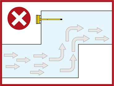
Figure 1. Duct sensor installed in a dead leg, leading to inaccurate measurements
Condensation
If you have problems with condensation, they will get worse if you mount your sensor pointing downwards. Condensation usually occurs at the point where the duct sensor is installed into the duct, and if the sensor is pointing downwards, the condensate water will then flow downwards onto the sensor and distort your readings – and maybe even cause corrosion or permanently damage the sensor. Sensors should be mounted horizontally or if they have to be tilted, ensure they are tilted upwards and not downwards.
Humidity sensors are quite often used to control humidification. A spray humidifier, for example, sprays small water droplets, and it takes some time for these small droplets to evaporate. Mounting duct sensors too close to humidifiers causes the water droplets to be sprayed onto the humidity or temperature sensors. The water droplets build up and the condensate in the sensor affects the accuracy of the measurements. In the worst case the sensor can be completely ruined; at the very least, it will be impossible to control anything using measurements taken by a sensor that is constantly affected by condensation. The minimum distance between a humidifier and a duct sensor depends on flow rates and humidifier type, but as a general rule of thumb, duct sensors should be installed about five meters away from humidifiers.
It’s often a good idea to make a feedthrough hole when mounting a duct transmitter, so that you can later use a reference probe to check the readings (Figure 2). The hole can be covered with duct tape when not in use.
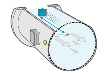
Figure 2. Adding a feedthrough hole when mounting a duct transmitter allows readings to be checked with a reference probe.
For CO2 and gas sensors, a quite common design is so-called flow capture. This is when part of the duct air flow is captured and directed into the electronics box, outside the duct, where the actual measurement is carried out. The air is then returned back to the duct, assuming the feedthroughs, lids and the mounting to the duct itself are airtight. If there is a leak, the air flow will most likely not go into the electronics box at all, so you are measuring the outside air instead of the air in the duct.
There are some sensors that are designed to measure inside ducts, and these are less prone to the kinds of errors caused by leaks.
Stay tuned to our January post of common pitfalls when installing HVAC sensors focusing on outdoor humidity and CO2 sensors.
Comment
Add new comment