Getting set up with Modbus


Getting set up with Modbus
In the second in our series of blog posts on Modbus, we show you how to get started in a short introduction video that covers testing and configuration. We then go on to discuss prototyping and commissioning.
You can watch the short video here.
Build a prototype
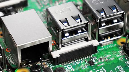
Now that you’ve established that your computer and probes are talking to each other, you can connect them to your systems, so the next step is typically to build a prototype. For instance, you can do this using the Raspberry PI platform, which has USB ports for connecting Vaisala USB cables to test Modbus RTU and a LAN port for testing Modbus TCP/IP. The recommended languages are Python or Node-RED, both of which have free, open libraries (PyModbus and Node-red-contrib-modbus respectively) for communicating with Modbus.
While the Raspberry Pi platform is fine for testing, it’s not suited to an industrial environment, so you’ll probably need something more robust such as a PLC; depending on the model, the PLC may also require a separate module to provide RS-485 access.
Check your Modbus communication settings
To avoid communication issues, all devices in a network should use the same communication parameters and have unique Modbus device addresses, which must be set manually. The Modbus protocol uses function codes to exchange values between the Modbus master and the slave devices. For instance, the master can communicate the process pressure value to the probe, which can then use this information to take a more accurate humidity reading. Because Modbus registers are vendor-specific, the values may be found at different addresses depending on the manufacturer. Another potential pitfall to watch out for is that while Modbus numbers the registers starting from one, some Modbus systems use values that start from zero, meaning that some trial and error may be required. To help with this, Vaisala products come with test registers for integer values, floating points, and text strings.
Commission your new system
Here is a checklist of things to keep in mind when carrying out commissioning:
- Communication settings need to be correct
- Wiring must be correctly connected, with a signal ground that passes through its own wire in the cable, not the chassis of the device
- All slave addresses must be unique when using multiple instruments
Once these initial checks are complete, you can test whether the slave devices provide an answer to the Modbus query. If there’s no answer, try to get the communication working with another Modbus master such as your PC and service cable. This can help to identify the source of the problem. The next question to consider is whether you got the expected response. If not, you can check the test registers to ensure that you’re requesting information from the correct address and, in the case of float value, that the endianness is correct.
Communicating with a PLC
Every PLC brand has its own way of implementing function blocks and libraries for Modbus communication, so it’s not possible to give any generic instructions on how to build the communication logic. However here are two cheat sheets for building successful communication with two widely used PLCS:
Allen-Bradley Micro820 Modbus RTU Guide
Siemens S7-1200 Modbus RTU Guide
That’s it – you’re all set up
Once you’ve carried out any necessary corrective actions, you should then have the expected response, meaning that from now on the system will respond correctly with no signal transmission errors. However, if you’re still having issues after going through these initial steps it’s probably time to call the manufacturer of the slave device to investigate the issue.
Learn more about Prototyping with Modbus or Contact us for more information.
Add new comment