Reliable CO₂ measurements for repeatable cell culture results
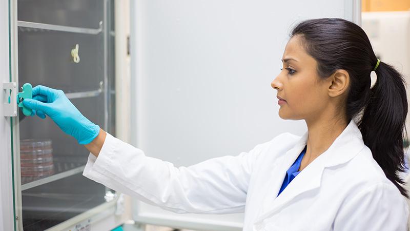
CO₂ incubators are used in laboratories to grow and maintain biological cultures—such as cells, bacteria, or tissues—under specific conditions. They’re essential tools in biological, microbiological, pharmaceutical, and medical research and production. They support microbiological studies, diagnostics, or fermentation research. In reproductive biology and IVF labs, incubators provide stable environments for embryo development. Pharmaceutical companies use incubators to stability test drugs or biologics and document how these materials react to prolonged exposure to various environmental conditions.

Controlling Critical Conditions in CO₂ Incubators
Typical conditions:
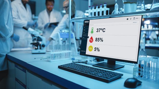
- CO₂ concentration of 5% - a higher concentration of 10% is occasionally used in some applications; however, measurement and control capability typically range between 0 and 20%
- Temperature of 37 °C (98.6 °F)
- Relative humidity of over 90%
Contamination control starts with knowing—instantly and accurately—what’s happening inside your incubator. Reliable measurement of CO₂, temperature, and humidity is the first line of defense against contamination. Our sensors deliver real-time data, so you can act before small deviations become big problems and protect your cultures from risk.
Key parameters: The foundation of reproducible cell cultures
Temperature & Humidity
Maintaining consistent temperature, humidity, and CO₂ concentration is essential for reliable incubator performance. Temperature control is typically achieved using a heating element and a high-speed fan to ensure uniform airflow, which also helps evenly distribute moisture and CO₂ throughout the chamber.
High relative humidity prevents sample desiccation but managing RH can be challenging. Many incubators use a water pan in the chamber to maintain humidity through evaporation. If the water temperature is lower than the chamber air, condensation can be minimized—though keeping humidity stable is still difficult, especially after door openings. Standing water also introduces a contamination risk if microbial growth occurs. An alternative is a humidity-controlled atomizer; this allows precise moisture levels but requires highly accurate RH measurement.
Carbon dioxide
Among all incubator conditions, carbon dioxide is often the most demanding to control. CO₂ is introduced to maintain a set concentration, and achieving stable levels depends on a combination of a high-quality CO₂ sensor, optimal sensor placement, and an effective control algorithm. Without reliable CO₂ control, cell growth conditions can drift, jeopardizing experiment integrity and reproducibility.
Contamination Control
Stable CO₂, temperature, and humidity are critical for preventing microbial growth and ensuring culture viability. Our sensor’s high accuracy and stability help you maintain optimal conditions—reducing the risk of contamination events and supporting reliable, repeatable results.
CO₂ Measurement Technology
There are two types of carbon dioxide installation methods: sampling and in-situ. Sampling measurement refers to, for example, pumping an air sample from the cabinet into the sensor with a help of tubing and a pump. When the sensor is located inside the cabinet, it is an in-situ measurement, which is often the preferred option because it requires fewer components, and it has a faster response time. The sensor, though, must always withstand high humidity and temperature.
Depending on the technology used, there are also other parameters that affect the carbon dioxide measurement. Infrared CO₂ measurement is based on a calculation of actual carbon dioxide molecules, in a specific gas density. Pressure and temperature affect gas density and therefore have an impact on the measurement reading. Based on the ideal gas law, the sample gas expands at a higher temperature and therefore shows a lower CO₂ concentration than the same sample at a lower temperature.
In addition, at lower pressure, such as high-altitude locations, the same CO₂ concentration will show too low readings. Humidity and oxygen have a minor effect on measurement accuracy, but usually this is not significant. Vaisala has introduced several ways to automatically compensate for all the above-mentioned phenomena.

Best Practices for CO₂ Sensor Placement
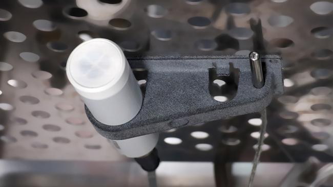
Correct placement of the CO₂ sensor is critical for accurate and reliable measurements. The sensor should be positioned in a representative location within the incubator—away from the CO₂ gas inlet, heating elements, and localized cold spots such as water pans or humidifiers. Corners of the chamber are also suboptimal due to limited air circulation.
Sensor accessibility is another important consideration. Placement should allow for easy removal during cleaning or maintenance and ensure that items placed in the incubator do not obstruct airflow or sensor function. A minimum clearance around the sensor is recommended to avoid measurement interference.
A proper seal of the environment is essential and using a feedthrough line to place the sensor within the incubator helps prevent heat loss and the formation of cold spots, which can lead to condensation inside the sensor and compromise performance. Inadequate sealing not only increases the risk of water accumulation but also creates surfaces where contamination can develop, making effective cleaning more difficult.
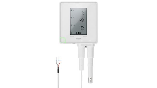
An optional flat probe cable allows you to place the sensor directly inside the incubator chamber, without compromising the door seal. This ensures you get true, in-situ readings—no risk of leaks, no need to prop the door open, and no disturbance to the environment. Maintaining the integrity of the incubator seal prevents external contaminants from entering and ensures that environmental readings reflect the actual conditions experienced by cultures, not just the air outside the chamber.
For optimal incubator performance, isolating the chamber from external temperature fluctuations is as important as precise sensor placement.

How CARBOCAP® NDIR sensors work
The Vaisala CARBOCAP® sensor uses non-dispersive infrared (NDIR) technology with a unique single-beam, dual-wavelength design to measure carbon dioxide (CO₂) accurately and reliably. It consists of three core components: an infrared (IR) light source, a Fabry-Perot Interferometer (FPI), and an IR detector. The IR light source emits light across a range of wavelengths, which travels a fixed optical path to the detector. Positioned in front of the detector, the FPI acts as a tunable optical filter, allowing only specific wavelengths of light to reach the detector at any given time.
CO₂ molecules absorb infrared light at a specific wavelength (around 4.26 μm). The sensor alternates between measuring this absorption wavelength and a nearby reference wavelength that is not affected by CO₂. By comparing the light intensity at these two wavelengths, the sensor determines the CO₂ concentration.
This dual-wavelength measurement compensates for potential drift due to aging components, contamination, or environmental changes—ensuring long-term stability and accuracy without the need for frequent recalibration.

Efficient, Reliable CO₂ Measurement with CARBOCAP® Technology
During operation, the CARBOCAP® sensor’s Fabry-Perot Interferometer (FPI) alternates between two wavelengths—one absorbed by CO₂ and one reference wavelength. The difference in detected light intensities reflects the CO₂ concentration. Calibration is performed using pure nitrogen and a known CO₂ concentration to define the response curve.
The single-beam, dual-wavelength design uses just one light source and one IR detector, eliminating alignment errors common in dual-beam systems. The micromachined FPI has no moving parts, offering superior reliability over mechanical chopper-wheel designs.
The sensor features Vaisala’s Microglow infrared source, which provides greater stability, faster response time, and 50% longer operational life compared to traditional incandescent sources—all while consuming just 25% of the power. Microglow’s stable output ensures long-term measurement accuracy, and its compact design allows direct integration onto circuit boards for efficient manufacturing.
Why Temperature and Pressure Compensation Matters in CO₂ Measurement
NDIR CO₂ sensors measure mole density—the number of CO₂ molecules in the optical path. To provide volume-based readings (e.g., %CO₂), the sensor converts mole density to volume concentration using calibration conditions: typically, 1013 hPa and 25 °C.
However, since gases are compressible, their density changes with temperature and pressure. If measurement conditions differ significantly from calibration conditions, the sensor output must be compensated; otherwise, accuracy will be affected.
This compensation relies on the ideal gas law and Dalton’s Law of Partial Pressures, which states that the total pressure of a gas mixture equals the sum of the partial pressures of its components. Tables 1 and 2 illustrate how uncorrected changes in temperature and pressure can impact CO₂ readings.
| Ptotal | = | P1 + P2 + P3 ... |
Understanding partial pressure & the need for compensation
In a gas mixture like air, each component exerts a partial pressure based on its volume fraction and the total pressure. For example, at sea level (1013 hPa), carbon dioxide at 0.04% volume has a partial pressure of about 0.405 hPa. At higher altitudes, such as Denver (834 hPa), the same 0.04% CO₂ results in a lower partial pressure (0.334 hPa), even though the concentration remains unchanged. Because NDIR sensors measure mole density (not volume %), changes in pressure and temperature affect accuracy. Lower pressure means fewer molecules in the same volume, reducing the measured signal. Similarly, as temperature decreases, mole density increases.
To ensure accurate volume or ppmv readings, CO₂ sensors must compensate for temperature and pressure variations. Most Vaisala CO₂ transmitters include an integrated temperature sensor for automatic compensation. Optional settings for oxygen and humidity compensation are also available, though their effects are minimal. The error caused by pressure variations due to local weather systems is typically small, and the default compensation setting of 1013 hPa works well near sea level. However, pressure should be taken into account at higher altitudes.
Tables
Table 1. Effect of uncompensated pressure changes of %CO2 readings in an NDIR sensor according to ideal gas law. Instruments calibrated at 25 ˚C and 1013 hPa.
Altitude above sea level | Pressure (hPa) | Measurement concentration (%CO2) | Corrected concentration (%CO2) | Difference (%CO2) | |
feet | meters | ||||
0 | 0 | 1013 | 5.00 | 5.00 | 0.00 |
500 | 153 | 992.8 | 4.90 | 5.00 | 0.10 |
1000 | 305 | 979.1 | 4.83 | 5.00 | 0.17 |
1500 | 458 | 958.4 | 4.73 | 5.00 | 0.27 |
2000 | 610 | 937.7 | 4.63 | 5.00 | 0.37 |
2500 | 763 | 923.9 | 4.56 | 5.00 | 0.44 |
3000 | 915 | 903.2 | 4.46 | 5.00 | 0.54 |
3500 | 1068 | 889.4 | 4.39 | 5.00 | 0.61 |
4000 | 1220 | 868.7 | 4.29 | 5.00 | 0.71 |
4500 | 1373 | 854.9 | 4.22 | 5.00 | 0.78 |
5000 | 1526 | 834.3 | 4.12 | 5.00 | 0.88 |
5500 | 1679 | 820.5 | 4.05 | 5.00 | 0.95 |
6000 | 1831 | 806.7 | 3.98 | 5.00 | 1.02 |
Table 2. Effect of uncompensated temperature changes on %CO2 readings in an NDIR sensor according to ideal gas law. Instruments calibrated at 25 ˚C and 1013 hPa.
Temperature (˚C) | Measured concentration (%CO2) | Corrected concentration (%CO2) | Difference (%CO2) |
25 | 5.00 | 5.00 | 0.00 |
26 | 4.98 | 5.00 | 0.02 |
27 | 4.97 | 5.00 | 0.03 |
28 | 4.95 | 5.00 | 0.05 |
29 | 4.93 | 5.00 | 0.07 |
30 | 4.92 | 5.00 | 0.08 |
31 | 4.90 | 5.00 | 0.10 |
32 | 4.89 | 5.00 | 0.11 |
33 | 4.87 | 5.00 | 0.13 |
34 | 4.85 | 5.00 | 0.15 |
35 | 4.84 | 5.00 | 0.16 |
36 | 4.82 | 5.00 | 0.18 |
37 | 4.81 | 5.00 | 0.19 |

Built-In Compensation for Accurate CO₂ Readings
When measurements are taken under conditions that differ from calibration (typically 25 °C and 1013 hPa), accuracy may be affected. Volume percent readings can be corrected using a simple formula based on the ideal gas law.
ccorrected (% / ppm) = cmeasured((% / ppm)) x ρ / 1013 x 298 / ((273 + t))
where:
ρ = ambient pressure (hPa)
t = ambient temperature (°C)
Vaisala CARBOCAP® CO₂ probes GMP231 and GMP251 feature built-in temperature compensation and allow optional pressure, oxygen and humidity compensation for optimal accuracy. GMP231 is also equipped with an internal pressure sensor for active pressure compensation. Compensation settings can be defined at the time of ordering or adjusted later using a handheld device or service cable. Detailed instructions are available in the user guide.

How to keep sample lines condensation-free in incubator field check | calibration
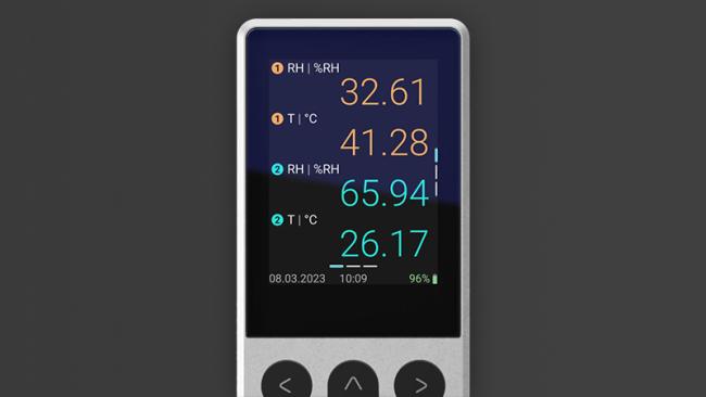
The Indigo80 handheld indicator offers two sampling methods: diffusion and pump aspirated. Pump aspiration is used when direct diffusion is not feasible. When sampling from high-humidity environments like incubators, precautions are necessary to prevent condensation, which can damage the NDIR sensor and pump components. Condensation often occurs when warm, humid air is drawn into cooler ambient conditions. To prevent this, use a sample tube made of Nafion® (Vaisala Part No. 212807GM), which helps remove moisture from the gas sample before it reaches the sensor.
Nafion® tubing selectively removes water through pervaporation, where moisture passes through the membrane and evaporates into the surrounding air. This drying process follows first-order kinetics and typically completes within 100 to 200 milliseconds, making it ideal for humid samples drawn to room temperature. Only a short length of tubing is needed to significantly reduce sample humidity. For more details, visit www.permapure.com.
Note: Nafion® is a DuPont copolymer of tetrafluoroethylene (Teflon) and a sulfonic acid derivative.
The Vaisala CARBOCAP® portable CO2 probe with pump sampling (GMP80P)
With the GMP80 pump sampling unit, you can spot check active incubators without opening the door. The sampling tube feeds from inside the chamber to a handheld Indigo80, allowing you to verify CO₂, temperature, and humidity without disrupting the controlled environment. This reduces the need to open incubator doors, minimizing the risk of airborne or contact-based contamination, and enables rapid, non-invasive checks—ideal for routine audits or when contamination is suspected.
|
|
|
|
|
|
|

Getting CO₂ monitoring right: From sensing to sampling
Accurate control, measurement and validation of CO₂ concentration in incubators are critical to maintaining optimal conditions for biological research and pharmaceutical applications. Understanding the effects of temperature, pressure, humidity, and sample handling—especially when using pump sampling with drying tubing—is essential for reliable CO₂ monitoring.
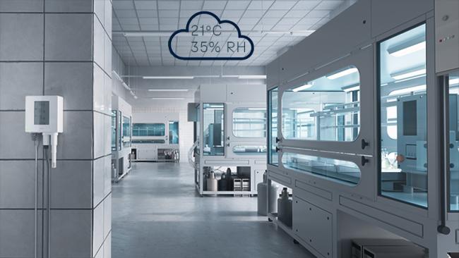
A sudden CO₂ drop or humidity spike can signal a door left ajar or a failing seal—both common sources of contamination. Our viewLinc monitoring system alerts you to these changes instantly, so you can intervene before contamination occurs and safeguard your work.
Technologies like Vaisala’s CARBOCAP® sensor, combined with proper sensor placement and built-in compensation for environmental variables, ensure precise and stable measurements. By following best practices for sensor installation and sample line management, and with devices like the Indigo80 handheld indicator, laboratories can maintain consistent incubator conditions that safeguard the integrity and reproducibility of their work.

Webinar: CO2 Incubators: Precise Control & Reliable Monitoring
Join Vaisala experts to learn why CO₂ stability is critical for cell viability and compliance. Explore incubator roles, sensing technologies, calibration, and why monitoring alongside control ensures reproducible results in demanding life science applications.
Incubator Solutions
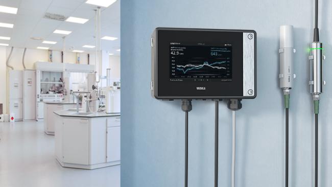
Indigo500 Series Transmitters
The Vaisala Indigo500 series transmitters are host devices for Vaisala Indigo-compatible, stand-alone smart probes. The Indigo500 series include multi-functional Indigo520 transmitter and Indigo510 transmitter with basic features.
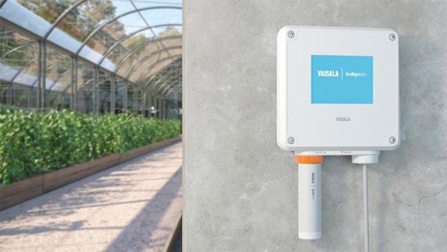
Indigo200 Series Transmitters
Vaisala Indigo200 series transmitters are host devices for displaying measurement values from Vaisala's Smart Humidity, Temperature, Dew Point, Moisture in Oil, CO2 and vH2O2 probes.
Indigo80 Handheld Indicator
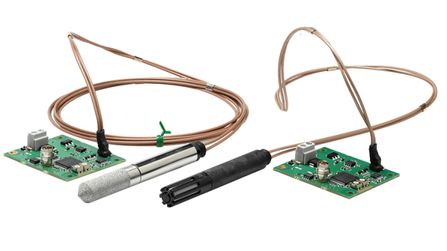
CO₂ Probe GMP251
The Vaisala CARBOCAP® Carbon Dioxide Probe GMP251 is an intelligent, stand-alone, %-level probe for measuring CO2 in life science incubators, cold storage facilities, fruit and vegetable transportation, and in all demanding applications where stable and accurate percentage-level CO2 measurements are needed.
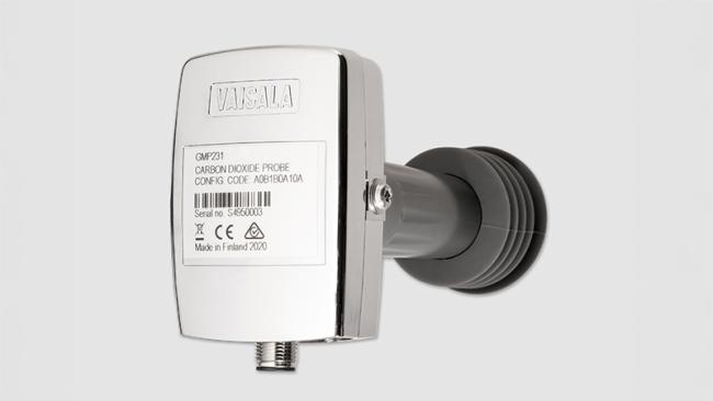
CO₂ Probe GMP231
The Vaisala CARBOCAP ® Carbon Dioxide Probe GMP231 is designed to provide incubator manufacturers with accurate and reliable carbon dioxide measurements and sterilization durability at high temperatures, up to 180 °C.
Humidity Module HMM100
viewLinc Monitoring, Alarming and Reporting Software
viewLinc Cloud SaaS monitoring system