How to select the right humidity instrument for your high-humidity application
While Vaisala HUMICAP® technology can withstand condensation, it still needs time to recover from the effects of moisture before it can once again provide reliable measurements. Typical applications where high humidity or occasional condensing are expected include drying processes, test chambers, combustion air humidifiers, meteorological measurements, and fuel cells.
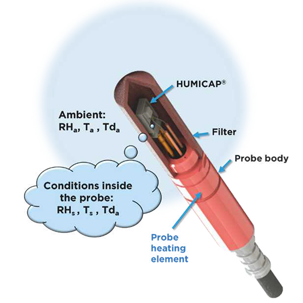
Keeping measurements accurate and reliable even in condensing environments calls for Vaisala’s condensation prevention technology. A warmed probe keeps the sensor continuously above the ambient temperature, ensuring condensation never forms.
The disadvantage of probe heating is that relative humidity can no longer be measured because the sensor is heated up above the ambient temperature. In this state, independent humidity parameters can be measured, such as dew point or mixing ratio. However, it is also possible to measure relative humidity using an additional temperature sensor with our Indigo520 transmitter.
Operating principle
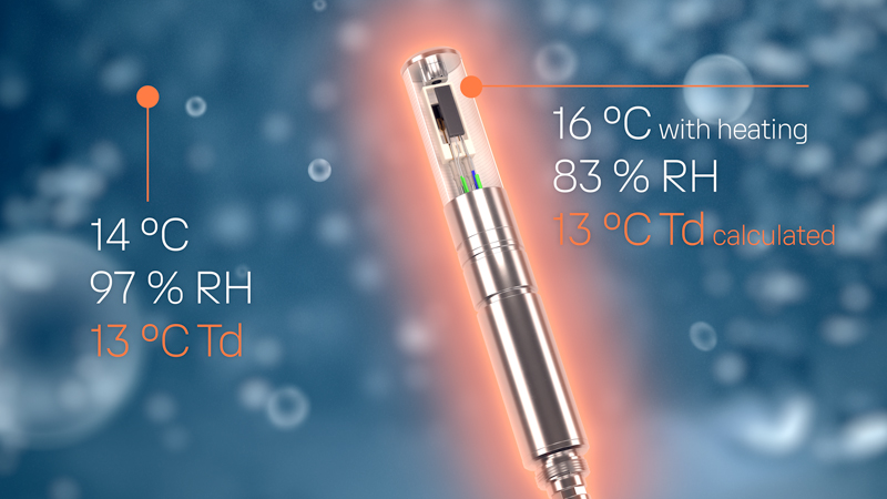
The heating element inside the probe body heats the entire probe. In this illustration, the probe and filter are glowing red to illustrate how the probe warming keeps the microclimate inside the filter at an elevated temperature. The actual temperature is only a few degrees above the ambient temperature, as seen in the example below:
Ambient Conditions:
Ta = 14 °C
RHa = 97% RH
Tda = 13 °C
HMP7 Warmed Probe:
Ts = 16 °C
RHs = 83% RH
Tda = 13 °C (calculated)
As shown in this example, heating does not affect dew point.
Dewpoint is the temperature where condensation begins, or where the relative humidity would be 100%, if the air was cooled.
The 'relative' in relative humidity expresses the relation between the amount of water vapor present and the maximum amount that is physically possible at that temperature.
Note: The HMP7 Warm Probe mode when used by itself will only output dew point temperature digitally (Modbus RTU over RS-485) or offer analog outputs when combined with any Indigo Transmitter. If Relative Humidity and Temperature are desired, then the separate ambient temperature probe (TMP1) must be ordered with the Indigo520 transmitter to calculate humidity from the dew point and temperature readings.
Conversion from HMT337WP (Warmed Probe) to an INDIGO Solution
For current high humidity applications using the HMT337WP, we recommend using our Indigo520 transmitter with the TMP1 and HMP7 probes with condensation prevention mode turned on. The new Indigo platform is built on the same measurement technology as its predecessor. The most significant and widely desired feature of the Indigo platform is the interchangeability of the smart probes. Many functionalities that were traditionally located inside the transmitter are now built into the smart probe instead, allowing for field swapping and cross-functional configurations. The following pictures illustrate the basic components of the previous and new measurement instruments. The probe head dimensions, filters, and installation accessories are identical, which means that, the HMP7 humidity probe fits the same process connection as the HMT337 probe.
HMT337 Transmitter Components
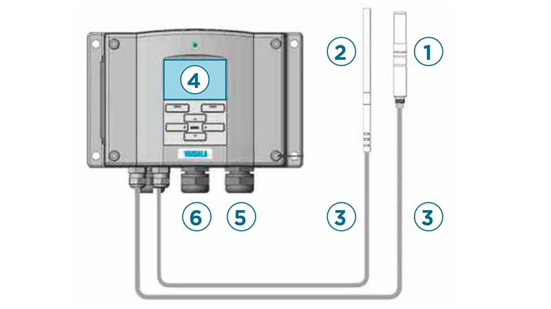
- Warmed Humidity Probe (Dew point output)
- Temperature Probe
- Fixed Cables from Probe to Transmitter
- Options for 2,5,10 and 20m lengths
- Transmitter
- Options for display or no display
- Input Power Cable Gland
- Options for 24Vac/dc, 100-240 Vac
- Output Signals Cable Gland
- 2 or 3 Analog outputs
- RS-232 or RS-485 or LAN
- 2 Relays
- HM70 Compatible service port
Indigo520 Transmitter Components
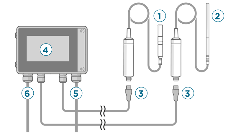
- HMP7 Warmed Humidity Probe (Dew point output)
- TMP1 Temperature Probe
- Fixed Cables from Probe to Transmitter
- Options for 1,3,5 and 10m lengths
- Transmitter
- Options for display or no display
- Input Power Cable Gland
- Options for 24Vac/dc, 100-240 Vac, PoE+
- Output Signals Cable Gland
- 4 Analog outputs
- Ethernet Modbus TCP/IP
- 2 Relays
- Built in Webserver
- Service port**
- Analog input**
- **To be added
History of Warm Probe Technology
Warmed probe technology was first developed by Vaisala over 25 years ago to address difficult outdoor humidity measurements for meteorological applications and then modified for industrial applications. In industrial applications with high-humidity, the temperature can change faster resulting in condensing conditions. The warmed probe technology eliminates downtime due to condensation and provides continuous measurement at condensing or saturating conditions.
The Indigo520 transmitter is an industrial-grade, robust transmitter that accommodates 1 or 2 Vaisala Indigo compatible probes for humidity, temperature, dew point, carbon dioxide, hydrogen peroxide, and moisture in oil measurements. The transmitter can measure barometric pressure with an additional module. TMP1 is designed for demanding temperature measurements in industrial applications, where accuracy and robustness are essential. HMP7 is designed for applications that involve constant high humidity or rapid changes in humidity, where measurement performance and chemical tolerance are essential. Together, this system can provide you with consistently accurate readings that you can trust. Please reference the below table that highlights their features.
| Product | HMP7 | TMP1 | Indigo201 + HMP7 | Indigo520 + TMP1 & HMP7 | HMT317 | HMM170 |
| Probe warming | Yes | Used for Temperature compensation | Configurable | Configurable | Configurable | Configurable |
| IP rating | IP66 | IP66 | IP66 | IP66 | IP66 | N/A |
| Ambient temperature sensor allows RH calculation | ** Possible with external temperature measurement | No | No | t) Configurable | No | ** Possible with external temperature measurement |
| Available measurement parameters | Td, Tdf, x, ppm, pw **(RH, T, a, Tw, pws, h, dT) | T | t) Td, Tdf, x, pw | Td, Tdf, x, pw t) (RH, T, a, Tw, pws, h, dT) | Td, Tdf, x, pw | Td, Tdf, x, ppm, pw **(RH, T, a, Tw, pws, h, dT) |
| Supply voltage | 18 ... 30 VDC | 10 ... 35 VDC | Configurable: 10 ... 35 VDC, 24 VAC | Configurable: 10 ... 35 VDC, 24 VAC, 100 ... 240 VAC, 50/60 Hz | 10 ... 35 VDC | 15 ... 35 VDC |
| Digital output | RS-485: Modbus RTU | RS-485: Modbus RTU | None | Modbus TCP/IP, web based interface | RS-232: serial ASCII | RS-485: Modbus RTU |
| Analog output | None | None | 3 x Assignable Analog outputs | 4 x Assignable Analog outputs | 2 x | 3 x |
| Display | No | No | Optional | Optional | No | No |
| Parametrization | Insight software | Insight software | 273956 or USB-C | Touch Screen or LAN | Terminal program (e.g. Putty) | Insight software |
| USB cable (sold separately) | 242659 or USB2 | 242659 or USB2 | None, USB-C | 219690 or USB2 | 238607 | 219690 |
** Relative humidity calculation is possible by writing external temperature information on a Modbus register
t) Configurable: additional temperature probe needed
Probe installation
Depending on the application, there are different mounting accessories available:
Duct Mount
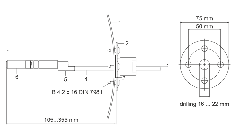
1 = Duct wall
2 = Flange
3 = Sealing ring
4 = Supporting bar (not included in the kit for HMT335)
5 = Probe attaching part (to be fixed to the supporting bar)
6 = Relative humidity probe
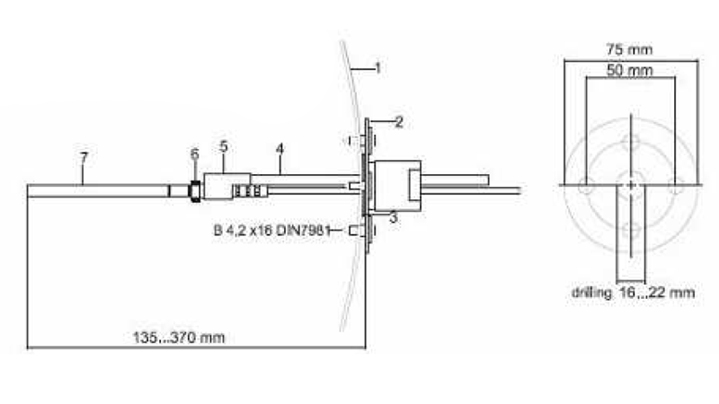
1 = Duct wall
2 = Flange
3 = Sealing ring
4 = Supporting bar
5 = Probe support (to be fixed to the supporting bar)
6 = Retainer bushing (to be fixed to the supporting bar)
7 = Temperature probe (to be fixed to the retainer bushing)
Duct installation kit 210697 (215003 for HMT337 temperature probe)
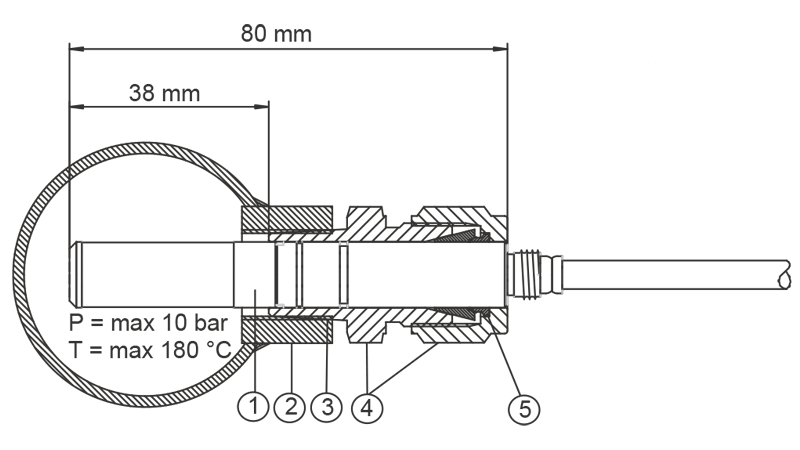
1 = Relative humidity probe
2 = Duct connector
3 = ISO 3/8'' or NPT 1/2'' thread
4 = Swagelok connector
5 = Ferrules
Pressure-tight Swagelok installation kits SWG12ISO38 with ISO3/8” or SWG12NPT12 with NPT1/2” thread (SWG6ISO18 with ISO1/8” or SWG6NPT18 with NPT1/8” thread for HMT337 temperature probe).
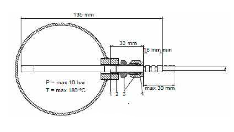
1 = T-probe
2 = Duct connector
3 = Swagelok connector
4 = Ferrules
Example of Climate Chamber Installation
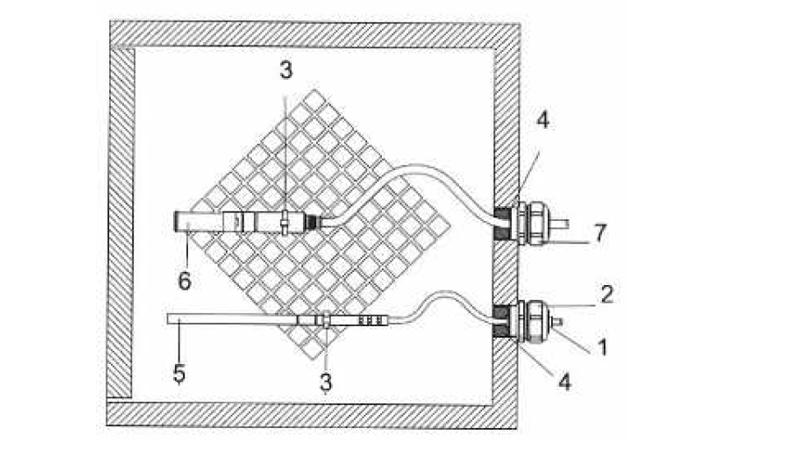
1 = PTFE sleeve
2 = Cable gland, example: AGRO 1100.12.91.065
3 = Stainless steel cable tie or similar fastener
4 = To be sealed (silicone)
5 = Temperature probe
6 = Relative humidity probe
7 = HMP247CG, Cable gland AGRO (available from Vaisala)
HMP247CG: Vapor-tight installation with cable gland.
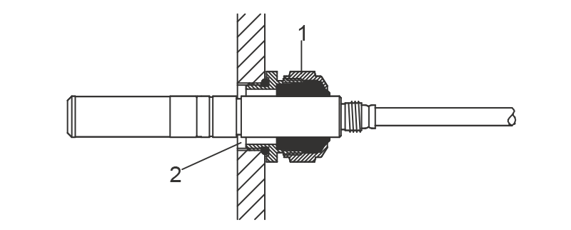
1 = AGRO 1160.20.145 (T = -40... +100 C) Not available from Vaisala
2 = In pressurized places, use a locking ring, example: 11 x 1 DIN471
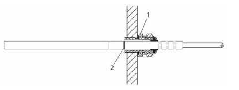
1 = Cable gland, for example: AGRO 1100.12.91.065
2 = In pressurized processes, use a locking ring, example: 6 x 0.7 DIN471
Insulation and leak-proof process connections
Choosing where to install a humidity probe can be challenging when there is high humidity combined with temperature variation.
For example, in a drying application where the exhaust air humidity is close to saturation (RH 95%) and the temperature is 40 °C, what happens when the sensor head is installed so that the filter is in the process and half of the sensor is in the 25 °C ambient temperature? In this situation even probe warming may not be able to compensate for the heat loss caused by thermal conduction through the metallic probe body; the heat loss will form a cold spot on the process side and condensation will result in inaccurate measurement. The solution here is to thoroughly insulate the probe.
If the process gas is colder than the ambient air it is critical to have a tight process connection for the probe. A leaking connection will allow warm and possibly humid air into the system, which can condensate near the sensor and cause measurement problems.
Extreme conditions, such as PEM fuel cell applications
There are also extreme applications where warming just few degrees above the ambient temperature is just not enough. One example of such application is a Polymer Electrode Membrane (PEM) Fuel cell. Application specific configurations can be found in the order forms of the HMP7 and HMT310-series. These configuration versions are designed to withstand the extreme conditions by heating the probe head at a higher power. It is also possible to use HMP7 and HMM170 in these applications, since the heating functionalities are freely configurable with the Insight PC software.
Summary
Sensor saturation can be avoided in high-humidity and condensing conditions by using an instrument that has probe warming technology. In addition to this, proper insulation and leak-free installation guarantees the best possible environment for reliable humidity measurement.
The comparison table in this article will help you to choose the right product for your application. More detailed product information and features can be found in datasheets, user manuals, and order forms.