Application note
Peroxide blending and dispense at CMP
Introduction
Chemical mechanical planarization (CMP) is the process of smoothing and polishing the wafer’s surface. This is done with the aid of an oxidizing agent, Hydrogen peroxide (H2O2) for example, which contains abrasive particles suspended in the carrier fluid. H2O2 oxidizes the silicon wafer surface to silicon dioxide. The polishing pad is then capable of polishing the wafer surface more efficiently because the newly oxidized layer is much softer than the silica.
The CMP slurries require mixing or dilution before use. Oxide polishing slurries are commonly purchased in concentrated form and diluted with water on-site to minimize shipping and labor costs. Some multicomponent polishing slurries may only be blended just prior to their use because of their short post-mix lifespan. In the latter case, it is essential to measure the H2O2 concentration of the mixed slurry, because altering the concentration of the slurry constituents will affect the chemical reaction rates and wafer polishing rate.
Process tools that drive the semiconductor manufacturing processes, like CMP, are referred to as critical process systems. They are typically fed from CMP slurry delivery systems operated by the fab’s facility management team. Automated chemical and slurry handling systems have tremendous implications to the safety, purity and up-time of the fabrication processes.
Application
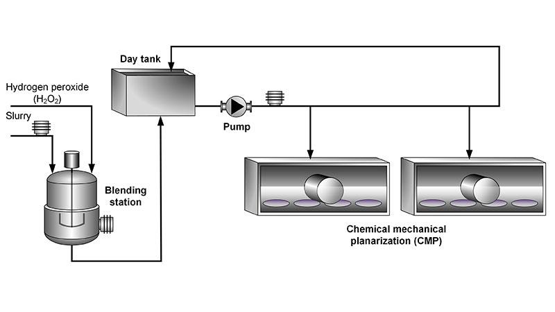
A typical blending and distribution system is composed of blend stations working in conjunction with each other to provide a continuous supply of slurry to multiple CMP polishers. Vaisala K-PATENTS® Semicon Refractometer PR-33-S is mounted as an integrated process metrology device, which measures the H2O2 content of the slurry during blending.
The system blends the slurry, DI water and H2O2, adjusting the mix to the required ratios. The raw slurry is pumped from a supply drum connected directly to the blending tank. The refractometer monitors the quality of the raw slurry and ensures it has a consistent density.
The slurry and other components are directed into the blend tank by weight or flow and recirculated in the blend loop until the mixture becomes homogenized. The blend must pass a quality analysis before the slurry can be distributed to the day tank and/or CMP tools.
With a traditional on-line auto-titrator, it could take anything from minutes to an hour before the slurry mixture can be validated as a qualified slurry blend. Optimizing the blend recirculation time by using a refractometer will eliminate unnecessary delays between slurry blending steps. Also, the qualification step which determines the CMP slurry’s H2O2 concentration can be shortened without sacrificing the slurry quality.
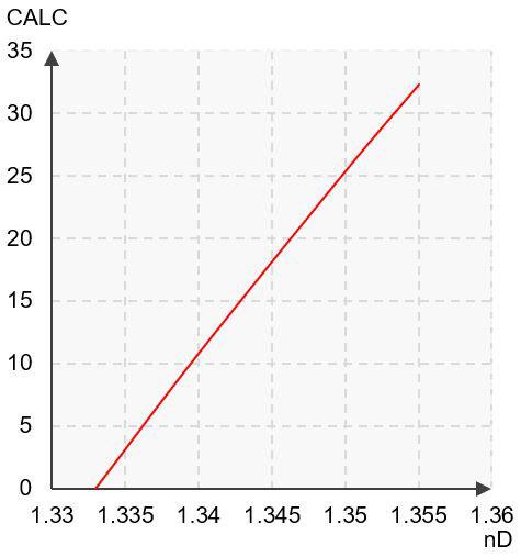
Chemical curve: Hydrogen peroxide R.I. per Conc% b.w. at Ref. Temp. of 20˚C
Typical end products
Hydrogen peroxide (H2O2), CMP slurry:
- Silicon wafers.

Instrumentation and installation
The Semicon Refractometer can be installed in a circulation line at the slurry blending station and/ or in the slurry dispensing line. A typical H2O2 concentration is 0-5 % by weight in the slurry and the process takes place at ambient temperature. The sensor can be installed into a vertical or a horizontal pipeline. The sensor should be mounted horizontally, so that the cable connection points downwards.

Vaisala K-PATENTS® Semicon Refractometer PR-33-S
A small footprint, PVDF covered sensor for cleanroom environment and integrated process tools. Monitors the chemical concentrations in real-time and provides an Ethernet output signal and immediate feedback to the control system. Connected through a modified PTFE flow cell body to the process by a 1/4”-1” Nippon pillar or flare fitting.
Measurement range
Refractive Index (nD) 1.3200 – 1.5300, corresponding to 0-100 % by weight.